| | Web Visualization > | | Chronicle article | Temporal Models | 2D Spacial Models | 3D Spacial Models | Parametric Models | Process Models |
Web Visualization for Teachers: 3D Spacial Models
Alistair B. Fraser
Comment: This document loads many objects. I have tried to
reduce download time by presenting low resolution versions.
But, some large objects may stream in slowly.
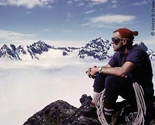 |
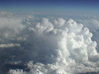
| Photograph, View from Mt. Slessy, 1964, shows perspective & aerial perspective |
Perspective
Since the 15th century, painters provided clues to the depth in a scene using perspective (decrease in angular size with distance) and aerial perspective (decrease in contrast with distance). Such techniques are still used when creating artificial representations, such as in paintings or three-dimensional computer models, but photographs capture them automatically.However, for many structures, such clues are of minimal help, because they depend for their effectiveness upon advanced knowledge of the characteristic size and transparency of objects. There are many circumstances where theses things are not known or are too variable to be of any use. Certainly this is true in my own discipline of meteorology where cloud sizes and opacity often render the devices of perspective and aerial perspective of little use in judging distance. Indeed, some famous illusions result, in at least in part from such difficulties in descrying the sky. However, anytime unfamiliar structures are encountered, such as occurs with mathematical structures or even microphotography, the difficulty in deducing the third dimension emerges. One solution to this problem is to use stereopsis.
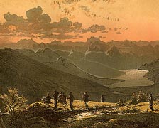
Watercolor, View from Righi, c.1860, uses perspective & aerial perspective
| Predator and prey: The hunted gains advantage from a large field of view and so has little overlap in the vision of the eyes. The hunter gains advantage from good estimates of distance and so uses overlapping vision to gain stereopsis. |
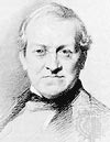
Man, the hunter, has stereoscopic vision, which enables the determination of distance independent of other clues. But, it is only effective over distances from about ten centimeters to maybe ten meters.This range, perfectly adequate for primitive hunting, is determined by the spacing of the eyes. In 1838, Sir Charles Wheatstone (yes, he of Wheatstone bridge fame) invented the stereoscope, a device which enabled him to combine separate views as might be seen by the two eyes, into a single stereoscopic view. This was created a year before photography became available to the world, so Wheatstone was not concerned with stereoscopic photography. Rather, it seems that he was attempting to represent the three-dimensional shape of mathematical structures. But with the advent of photography, it was not long before the viewing of stereographs became a parlor activity on a par with that of watching TV today. Wheatstone's device is in extensive use to this day to ease the interpretation everything from X-rays to aerial photographs. As early as 1860 it was used to make sense of stereo photographs of clouds and by 1890 there were even stereoscopic pictures of the Moon (those of you with an analytic turn of mind might wish to match the ingenuity of the person who did that).
Wheatstone
(1802-1875)
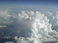
To represent this approach, I display a stereoscopic pair of photographs of a cumulus cloud. It was taken with a digital camera from a plane. A succession of images taken a few seconds apart gives an effective eye spacing of maybe a half kilometer which enables stereo vision to extent to perhaps 50 times that distance.
 |
 |
|
| For parallel viewing, fuse left & center images. For crossed-eye viewing, fuse center & right images. | ||
The images are presented in two different ways to cater both to those who prefer parallel fusion and to those who prefer crossed-eyed fusion. For over twenty years I have taught my classes how to do the crossed-eyed viewing and the whole class would enjoy a stereoscopic tour of the sky during which I could discuss features and processes not readily discernible in normal slides. I employed two slide projectors and two large projection screens; one need not constrain image size with this technique. The striking thing about this approach to facilitating the construction of spacial models of the atmosphere (or whatever you are illustrating) is that the computer seems to confer no particular benefit. When the time comes for my stereo tours of the sky, I still bring in my slide projectors. Certainly, capturing the images has been eased with digital camera, and editing has been eased with a computer, but for presentation purposes, the computer confers nothing. Yet, stereoscopic presentations provide one of the few ways to sort out structure (and thus ultimately process) in complex variable skyscapes or landscapes.
| Fly by the obelisk |
A frequently employed means of hinting at the three dimensional structure of an object is to use a flyby: in effect using a temporally changing view as a means establishing shape. For example here is a simple shape, an obelisk which sits on the main Penn State campus. The view is as might be seen by a dragonfly taking a tour. In the past, this technique was largely confined to those who used high-end architectural modeling programs and were entirely of artificial structures. But, life is getting simpler. This simple model was constructed in about two hours, including the time to take the four pictures of the obelisk upon which it is based (well, it is a simple structure, but sill....)
| Hurricane Erin, handle it
(it takes time to load) |
QuickTimeVR, the same protocol which provided the fist navigable panoramas also allows the navigation of a two-dimensional array of images. If these are images of an object and each column corresponds to a view at a particular azimuth, and each row a view from a different elevation, the result is palpably like that of manipulating a real object. It is far more effective than merely examining the same spacial array of images spread out before one. The object presented to the right is that of a hurricane. In the opening view, it is seen from above in the same way it is normally presented in satellite images. But you can grab it and turn it to obtain a vastly improved impression of its spacial structure. This approach can be very effective, but it suffers from having large file sizes (all those separate views) and so takes longer to download than, say using, say, a vector model. In some ways, this is like the flyby, above, but with the ability to control the view. QuickTimeVR objects can be linked to QuickTimeVR panoramas so that, say, one could represent a touring a museum in which one could pick up artifacts and examine them.
| Obelisk, handle it |
With vector graphics, an object is described by as a mathematical structure and it is then rendered in the browser by the plugin. As such there is much less to transmit and store, but much more to calculate. The obelisk to the right uses the Metastream 2 plugin available for both Mac (alas, only OS 8-9; there is no OS X version yet) and Windows . You can grab the obelisk and turn it in any direction. Click on the help button on the lower left to learn of other options such as zooming.
There are a number of discipline-specific vector graphics programs which greatly facilitate the construction and delivery of spacial structures characteristic of that field of study: e.g., mathematics, chemistry, architecture.
Note:The image, View from Righi, above is in the public domain.
| | Web Visualization > | | Chronicle article | Temporal Models | 2D Spacial Models | 3D Spacial Models | Parametric Models | Process Models |